 +86-573-86868360
 Inquiry
 English
 Español
 عربى
عربى

Content
Crawler crane steel structure components form the backbone of safe and efficient heavy lifting operations across construction, energy, and infrastructure projects. These components include the lattice boom, undercarriage frame, revolving superstructure, mast, and counterweight systems, all fabricated from high-strength alloy steel through precision cutting, robotic welding, and rigorous non-destructive testing. When manufactured to exact specifications with proper surface treatment and quality control, these steel structures deliver the load capacity, stability, and durability required for continuous operation in demanding environments.
Core Steel Structure Components
Boom and Lattice Structures
The boom serves as the primary load-bearing arm of the crawler crane, available in lattice and box-type configurations. Lattice booms use welded frameworks of high-tensile steel tubular chords that provide maximum strength with minimal weight. Typical chord dimensions range from 300mm by 300mm for smaller capacities to 1150mm by 1150mm at connection points for heavy-duty applications. These modular sections connect via high-strength pins, allowing configurations from 9 meters to over 130 meters depending on project requirements. Boom sections incorporate internal reinforcement ribs and anti-friction bearing sheaves to manage dynamic loads during lifting cycles.
Undercarriage and Crawler Frames
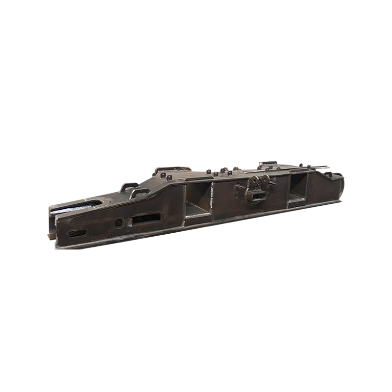
The undercarriage consists of a center frame and two crawler side frames, forming the foundation that distributes the crane's total weight across the ground surface. The center frame uses all-welded box-section construction from high-strength alloy steel, engineered to resist bending and torsional forces. Side frames feature retractable designs for transport flexibility, with track shoes made from heat-treated alloy steel castings. Track shoe widths vary from 700mm on compact models to 2000mm on large-capacity cranes, providing ground contact areas exceeding 200 square meters to maintain ground pressure below 80 kPa and prevent sinking on soft soils.
Revolving Frame and Superstructure
The revolving frame connects to the undercarriage through a slewing bearing and supports the boom, hoist mechanisms, and operator cabin. Fabricated as an all-welded steel structure with stress-relief treatment, this component requires precision-machined mounting surfaces to ensure smooth 360-degree rotation. The frame must withstand substantial torsional stresses during operation, particularly when lifting offset loads or working in windy conditions. Design specifications typically require yield strengths of 550 MPa or higher with full-penetration welds at critical load-path junctions.
Mast and Counterweight Systems
Superlift masts and counterweight systems provide the backward stability necessary for heavy lifts. Mast sections commonly measure 12 meters per module and use pin-connected lattice construction. Counterweight configurations range from individual blocks of 3600 kg to 8000 kg, with total counterweight reaching 18 tons or more depending on boom length and load radius. Dynamic balancing systems adjust counterweight position in real time to control load swing within 0.5 degrees during critical lifting operations.
Material Selection and Specifications
Selecting appropriate steel grades for each crawler crane component ensures structural integrity under extreme loading conditions. High-tensile structural steels dominate boom and mast fabrication, while alloy steels with enhanced wear resistance serve undercarriage applications. The following table outlines typical material specifications for major steel structure components.
| Component | Steel Grade | Yield Strength | Key Properties |
|---|---|---|---|
| Lattice boom chords | High-tensile structural steel | 690 MPa or higher | Lightweight, high buckling resistance |
| Undercarriage frame | High-strength alloy steel | 550 MPa or higher | Bending and torsion resistance |
| Track shoes | Heat-treated cast steel | 800 MPa or higher | Wear resistance, induction-hardened paths |
| Revolving frame | Structural carbon steel | 355 MPa or higher | Weldability, machinability |
| Mast sections | Fine grain structural steel | 690 MPa or higher | High fatigue resistance |
Material procurement requires strict inspection protocols including appearance evaluation, dimensional measurement, mechanical property testing, and chemical composition analysis. Only materials passing all inspections proceed to fabrication, ensuring that yield strength, tensile strength, and impact resistance meet design requirements for the intended load class.
Fabrication Process Workflow
Drawing Review and Process Design
Fabrication begins with comprehensive drawing review to verify dimension marks, connection methods, and technical requirements. Engineers develop detailed process plans that specify cutting sequences, welding procedures, and assembly jigs. For crawler crane components, process design must account for weld accessibility in box-section frames and the sequential build-up of lattice boom chords to minimize residual stress.
Precision Cutting and Edge Preparation
Steel plates and tubes are cut to specified dimensions using flame cutting, plasma cutting, or laser cutting depending on thickness and tolerance requirements. Thicknesses up to 50mm typically use plasma cutting for speed and accuracy, while thicker sections may require flame cutting. After cutting, beveling operations prepare edges for welding using mechanical processing or thermal cutting. Bevel angles and root openings are controlled within 1mm tolerance to ensure full penetration on critical joints.
Welding and Assembly
Welding represents the most critical stage in steel structure fabrication. Manual arc welding, gas-shielded welding, and submerged arc welding each serve specific applications based on material thickness and joint configuration. For main boom chords and undercarriage frames, robotic automation achieves first-pass qualification rates of 99.5 percent or higher, reducing defect rates and ensuring consistent penetration. Bolted connections complement welding in areas requiring future disassembly, with bolt hole machining held to H12 tolerance class and tightening torque verified with calibrated tools.
Forming and Stress Relief
Bending and forming operations shape plates into curved sections for boom bases and crawler frame housings. Plate rolling machines and press brakes achieve bending radii specified in drawings without cracking or excessive thinning. After welding, stress-relief heat treatment reduces residual stresses that could cause distortion or fatigue cracking during service. Components undergo correction procedures including mechanical pressing or flame straightening to meet flatness and straightness tolerances of 1mm per meter.
Surface Treatment and Corrosion Protection
Surface preparation begins with shot blasting or sandblasting to remove rust, oil, and oxides, achieving surface cleanliness grades of Sa 2.5. Anti-corrosion treatments include painting systems with epoxy primers and polyurethane topcoats, or hot-dip galvanizing for components exposed to harsh environments. Coating thickness typically ranges from 80 micrometers to 200 micrometers depending on environmental exposure class, ensuring protection against salt spray, humidity, and chemical contaminants.
Quality Control and Inspection Standards
Dimensional Accuracy and Tolerance
Dimensional inspection occurs at multiple stages from raw material verification through final assembly. Critical measurements include boom chord linearity, undercarriage frame squareness, and slewing bearing mounting surface flatness. Geometric tolerances for boom section connections are held within 0.5mm to ensure smooth pin insertion and load transfer. Track shoe pitch and roller path alignment are verified to prevent premature wear and track derailment.
Weld Integrity Verification
Non-destructive testing validates weld quality on all load-bearing joints. Ultrasonic testing and radiographic inspection detect internal defects such as porosity, slag inclusions, and incomplete fusion. Magnetic particle inspection identifies surface cracks in high-strength steel welds. Acceptance criteria follow structural welding standards requiring 100 percent inspection on boom chord welds and undercarriage frame main seams, with repair rates maintained below 2 percent of total weld length.
Mechanical Performance Testing
Finished components undergo mechanical testing to validate design assumptions. Tensile tests confirm yield strength and elongation meet material certificates. Charpy impact tests at -20 degrees Celsius or lower verify toughness for cold-climate operation. Load testing of assembled boom sections validates deflection limits, typically requiring that boom tip deflection under rated load does not exceed 1/500 of boom length.
Maintenance and Longevity Factors
Proper maintenance extends the service life of crawler crane steel structures beyond 20 years of active use. Key maintenance practices include:
- Regular inspection of boom chord welds and pin bores for fatigue cracks, particularly at connection points where stress concentration occurs
- Monitoring of undercarriage track shoe wear and roller path condition, replacing shoes when tread depth reduces below 10mm
- Touch-up painting of chipped or scratched coating areas to prevent localized corrosion that can propagate into structural sections
- Verification of bolt torque on counterweight connections and boom pendant attachments at 500-hour intervals
- Alignment checks for the slewing bearing interface after heavy lifts or transportation to ensure even load distribution
Manufacturers should provide detailed traceability records including material certificates, welding procedure specifications, and inspection reports for each component. This documentation supports predictive maintenance programs and ensures replacement parts match original specifications when repairs become necessary.
Conclusion
Crawler crane steel structure components demand meticulous attention to material selection, fabrication precision, and quality verification. From high-tensile boom chords to heavy-duty undercarriage frames, each element contributes to overall lifting performance and site safety. By adhering to rigorous cutting, welding, and inspection standards, manufacturers produce steel structures capable of sustaining decades of service in the most challenging construction environments. Buyers and operators who understand these technical fundamentals make informed decisions that protect both personnel and capital investment.