 +86-573-86868360
 Inquiry
 English
 Español
 عربى
عربى

Content
- 1 What a Coal Mill Steel Structure Actually Does
- 2 Core Steel Structure Components of a Coal Mill
- 3 Material Grades Commonly Used in Coal Mill Steel Structures
- 4 Common Failure Modes in Coal Mill Steel Structure Components
- 5 Fabrication and Dimensional Standards for Key Components
- 6 Inspection and Maintenance Priorities by Component
- 7 Key Considerations When Sourcing or Replacing Components
A coal mill steel structure is a load-bearing framework engineered to support rotating mill bodies, grinding mechanisms, drive systems, and auxiliary equipment under continuous dynamic and thermal stress. The steel structure is not a passive frame — it is a precision-engineered assembly where each component plays a defined structural role, and failure in any one part can halt production or cause catastrophic equipment loss. Understanding these components in detail is essential for procurement, maintenance planning, and structural inspection.
What a Coal Mill Steel Structure Actually Does
Coal mills — whether ball mills, vertical roller mills (VRM), or bowl mills — operate under severe mechanical conditions. The steel structure must simultaneously handle static dead loads exceeding 200–500 tons depending on mill size, dynamic loads from grinding vibration, thermal expansion from hot gas flows, and impact loads from coal feed variation.
The structure integrates the mill into the plant building, connects it to the drive train, and provides anchor points for dust sealing, classifier housings, and ductwork. Without a properly designed steel structure, alignment tolerances — often as tight as ±0.5 mm on bearing housings — cannot be maintained during operation.
Core Steel Structure Components of a Coal Mill
Mill Foundation Frame and Base Plate
The foundation frame is the lowest tier of the steel structure, anchored directly to the concrete foundation via anchor bolts and grout pads. It distributes mill weight and operational loads into the civil structure. Base plates are typically fabricated from Q345B or S355JR steel, with thicknesses ranging from 40 mm to 100 mm depending on applied load. Precision machined surfaces ensure the mill body sits level within 0.1 mm/m tolerance.
Main Bearing Support Structure
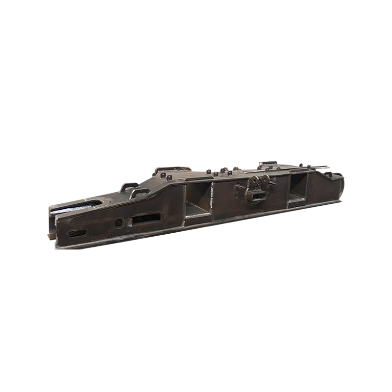
In horizontal ball mills, the main bearing pedestals are robust steel weldments that carry the entire rotating drum weight — which can reach 80–300 tons for large tube mills. These pedestals are machined to accept white metal or rolling element bearings and must resist both radial loads from mill weight and axial loads from thermal elongation.
In vertical mills, the equivalent structure is the gearbox support frame, which must also absorb torque reactions from the planetary or bevel-helical gearbox — torque values in large VRMs can exceed 3,000 kN·m.
Mill Casing and Shell Segments
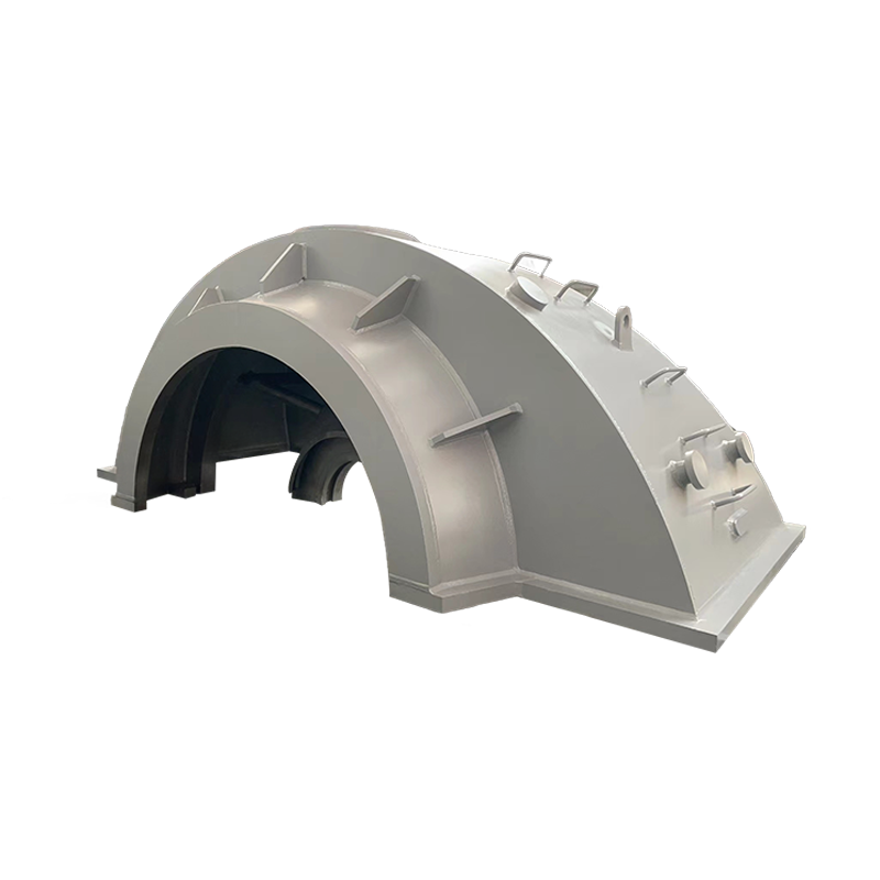
The mill shell or casing is a pressure boundary component as well as a structural one. For ball mills, the cylindrical shell is fabricated from rolled steel plate, typically 20–50 mm thick, with welded end walls. Shell segments are often supplied in sections of 2–6 meters in length for transportation, bolted or welded together on-site. Internal liners protect the shell from abrasion, but the steel shell itself must resist hoop stress from internal pressure differentials and bending stress from supported weight.
Access Platforms and Walkway Grating Structures
Operational and maintenance access platforms surround the mill body at multiple elevations. These are hot-dip galvanized steel grating structures supported by welded or bolted steel frames. Platform live load ratings typically comply with OSHA 1910.22 or EN 1991-1-1 standards, requiring a minimum 2.0 kN/m² distributed load capacity. Handrail posts are usually welded from 48 mm Schedule 40 pipe at 1,500 mm spacing.
Drive Support and Girth Gear Guard Structure
The drive arrangement — whether central drive, side drive with pinion, or direct drive — requires dedicated steel support structures. Pinion shaft bearing housings bolt onto precision-aligned steel plinths. The girth gear, which wraps around the mill shell and can be 6–12 meters in diameter, is protected by a bolted steel guard assembly fabricated from 4–6 mm sheet steel with inspection windows.
Classifier and Separator Housing Frame
In vertical coal mills especially, the classifier housing sits above the grinding table and requires its own structural support — a welded steel frame attached to the main mill body or building columns. These frames carry both the weight of the classifier rotor assembly and the aerodynamic loads from high-velocity air-coal streams typically running at 20–35 m/s through the classifier zone.
Ductwork and Pipe Support Brackets
Hot gas inlet ducts, coal outlet pipes, reject chutes, and recirculation lines are all anchored to the steel structure via welded or clamped bracket assemblies. These supports must account for thermal expansion — a 10-meter steel duct operating at 300°C will expand approximately 36 mm longitudinally — requiring sliding or spring-type supports at strategic locations.
Material Grades Commonly Used in Coal Mill Steel Structures
Material selection is not uniform across all components. Structural frames use standard structural steels, while wear-prone or high-stress components require upgraded grades.
| Component | Typical Steel Grade | Yield Strength (MPa) | Key Property |
|---|---|---|---|
| Foundation frame / base plate | Q345B / S355JR | 345 / 355 | Good weldability, high strength |
| Mill shell | Q345R / SA516-70 | 345 / 260 | Pressure vessel grade, impact resistant |
| Bearing pedestal / support blocks | Q390 / S420 | 390 / 420 | High load capacity, dimensional stability |
| Platform grating frame | Q235B / S235JR | 235 | Standard structural, cost-effective |
| Duct support brackets | Q345B / 16Mo3 | 345 / 275 | Elevated temperature service |
Common Failure Modes in Coal Mill Steel Structure Components
Understanding where failures occur helps prioritize inspection and maintenance budgets. The following failure modes are documented across operating coal mills worldwide:
- Weld fatigue cracking at the base plate-to-pedestal junction, caused by cyclic vibration — detectable via magnetic particle or dye penetrant testing during planned shutdowns.
- Corrosion and pitting on interior shell surfaces not covered by liners, particularly in zones where condensation forms during cold starts. Wall loss of 2–4 mm per year has been recorded in poorly maintained mills.
- Anchor bolt loosening in foundation frames due to dynamic loads and improper torquing during installation — a primary cause of base plate misalignment over time.
- Thermal distortion in duct support brackets operating above 250°C without adequate expansion allowance, leading to bracket cracking or duct flange leakage.
- Platform and stairway corrosion from coal dust and moisture exposure — hot-dip galvanizing with a minimum 85 µm zinc coating significantly extends service life compared to paint-only systems.
Fabrication and Dimensional Standards for Key Components
Steel structure components for coal mills are fabricated to tightly controlled standards. The following are typical tolerance requirements and applicable codes:
- Shell roundness tolerance: ≤3 mm deviation from nominal diameter, measured at every 1-meter interval along the shell length.
- Weld quality: Full penetration butt welds on mill shells are subject to 100% ultrasonic testing (UT) per AWS D1.1 or EN ISO 17638 standards.
- Machined bearing surfaces: Surface finish Ra ≤ 1.6 µm, flatness within 0.02 mm over the bearing contact area.
- Structural frame alignment: Column verticality within 1/1000 of column height, per GB50205 or AISC 303 erection standards.
- Base plate leveling: Grouted base plates must achieve ±0.5 mm elevation tolerance across the full frame footprint before equipment erection begins.
Inspection and Maintenance Priorities by Component
A structured inspection regime significantly extends service life and reduces unplanned downtime. Below is a recommended inspection frequency framework based on industry practice:
| Component | Inspection Method | Recommended Frequency | Critical Threshold |
|---|---|---|---|
| Base plate and anchor bolts | Visual + torque check | Every 6 months | Any bolt below 80% rated torque |
| Mill shell welds | UT / MPI | Annually | Any crack > 10 mm length |
| Bearing pedestal surfaces | Dial gauge measurement | Every 12–18 months | Settlement > 0.3 mm from baseline |
| Platform grating and handrails | Visual + thickness gauge | Every 12 months | Wall loss > 20% of original thickness |
| Duct support brackets | Visual + DPT at welds | Every 18–24 months | Any cracking or visible deformation |
Key Considerations When Sourcing or Replacing Components
Whether specifying new components for a greenfield project or procuring replacements for an existing mill, several technical factors are non-negotiable:
- Mill-type compatibility: A base frame designed for a ball mill cannot be adapted for a VRM without complete re-engineering. Always reference the original equipment manufacturer (OEM) drawing numbers.
- Material certification: Demand mill certificates (EN 10204 Type 3.1 minimum) for all load-bearing structural steel. Generic steel without traceability is a code compliance and safety risk.
- Surface treatment specification: Specify blast cleaning to Sa 2.5 (ISO 8501-1) prior to painting or galvanizing. Inadequate surface prep is the leading cause of premature coating failure in coal mill environments.
- Dimensional verification before erection: All machined mating surfaces should be dimensionally checked against the as-built survey before installation — especially after long-distance shipping, which can introduce distortion in large weldments.
- Spare parts stocking strategy: High-criticality components like bearing pedestals and shell segment sections should be held as on-site or near-site spares for mills in continuous 24/7 operation, given typical lead times of 8–20 weeks for custom fabrications.