 +86-573-86868360
 Inquiry
 English
 Español
 عربى
عربى

Content
- 1 The Boom: The Primary Load-Bearing Arm
- 2 The Mast and Gantry: Controlling Boom Angle and Load Moment
- 3 The Slewing Table: The Rotational Interface
- 4 The Track Frame: The Foundation of Stability
- 5 The Counterweight System: Managing Load Moment
- 6 Comparison of Core Structural Components by Function
- 7 Hoist Machinery Frame and Winch Mounting Structure
- 8 Structural Steel Grade and Welding Quality: Why They Matter More Than You May Think
- 9 What to Look for When Sourcing Crane Structural Parts
- 10 Maintenance Considerations That Start With Structural Design
A crane is far more than a machine that lifts heavy objects. It is a carefully engineered system in which every structural component plays a defined role in distributing load, maintaining stability, and enabling controlled movement. Whether you are specifying a new crawler crane for a major infrastructure project or evaluating replacement structural parts, understanding what each component does—and what it must be made of—will directly influence your purchasing decisions and long-term operational costs.
In this article, we walk through the essential structural components found in modern cranes, explain how they interact as a system, and highlight the material and manufacturing standards that separate reliable equipment from equipment that fails under pressure.
The Boom: The Primary Load-Bearing Arm
The boom is the most visible and mechanically stressed structural member on any crane. It extends outward from the crane body to position the hook over the load, and it must carry the full combination of the lifted load, its own dead weight, and dynamic forces created by swinging or wind pressure.
Most crane booms use a box-section construction—a hollow rectangular or square profile—because this geometry offers an excellent strength-to-weight ratio. The wall thickness and steel grade are calibrated to the crane's rated capacity. For crawler cranes operating in the 100-to-500-ton range, boom sections are typically fabricated from high-strength low-alloy (HSLA) steel with yield strengths between 690 MPa and 960 MPa.
Boom failures almost always originate from one of three causes: inadequate material grade, poor weld quality at section joints, or fatigue cracks developing at stress-concentration points. This is why reinforcement plates are welded at high-stress zones such as the heel pin connection and mid-span splice joints.
Lattice Boom vs. Telescopic Boom
The two dominant boom types serve different applications:
- Lattice booms — used on crawler cranes and large duty-cycle cranes. Offer greater reach (up to 120 m on large machines) and better fatigue resistance because stress is distributed across multiple chord members and diagonals.
- Telescopic booms — used on mobile and all-terrain cranes. Sections slide inside one another for compact transport but generate higher local stresses at the inner/outer cylinder interface, requiring precise tolerance control during manufacturing.
The Mast and Gantry: Controlling Boom Angle and Load Moment
The mast (sometimes called the A-frame or backstay mast) works in conjunction with pendant lines to control the boom angle and counteract the overturning moment created when a load is lifted at a significant radius. On crawler cranes, the mast height is a key factor in determining the maximum permissible load chart values.
A taller mast increases the vertical component of the pendant force, reducing the compression load on the boom. A 10% increase in mast height can allow a corresponding increase in permissible load at longer radii, which is why crane manufacturers offer multiple mast configurations for the same base machine.
Structurally, masts must resist both compressive loads (from pendant tension) and bending loads (from out-of-plane wind forces). Welded steel box sections or circular tube sections are both used, with the latter offering better torsional stiffness.
The Slewing Table: The Rotational Interface
The slewing table (also called the rotating platform or upperworks frame) is the structural platform on which the boom, mast, counterweight, hoist machinery, and cab are all mounted. It connects to the undercarriage through a large-diameter slewing ring bearing, allowing 360-degree rotation.
This component experiences some of the most complex loading of any crane structural part. During a lift-and-swing operation, it must simultaneously:
- Transmit the vertical load from the boom heel pin to the slewing ring
- React the overturning moment trying to tip the machine forward
- Transfer the counterweight reaction rearward to balance the load moment
- Support the slewing drive torque without distortion
Given this complexity, slewing tables are typically fabricated as welded steel structures with internal stiffening webs. Dimensional accuracy is critical: the slewing ring mounting surface must be flat within tight tolerances (typically ±0.5 mm over the full ring diameter) to prevent uneven bearing load distribution, which accelerates wear and can lead to bearing failure.
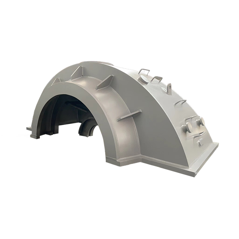
We manufacture Crawler Crane Slewing Table Carbon Steel Structural Parts engineered to meet these exacting standards, designed for compatibility with major crane platforms.
The Track Frame: The Foundation of Stability
For crawler cranes, the track frame (also called the carbody or undercarriage frame) is the structural base that distributes the entire crane load—machine weight plus lifted load—into the ground through the crawler tracks. It is literally the foundation on which everything else stands.
The track frame must handle ground bearing pressures that commonly range from 60 kPa to 150 kPa depending on crane size and configuration. It connects the left and right crawler assemblies through a central carbody, which includes the X-frame or H-frame structure that transfers loads from the slewing ring to both tracks.
Key Design Demands on the Track Frame
- Torsional rigidity — when one track is on higher ground than the other, the frame twists. Insufficient rigidity causes misalignment in the slewing ring and premature wear.
- Impact resistance — travel over rough terrain generates shock loads that the frame must absorb without permanent deformation.
- Fatigue life — track frames typically accumulate tens of thousands of operating hours; weld details at stress concentrations must be designed for a defined fatigue category.
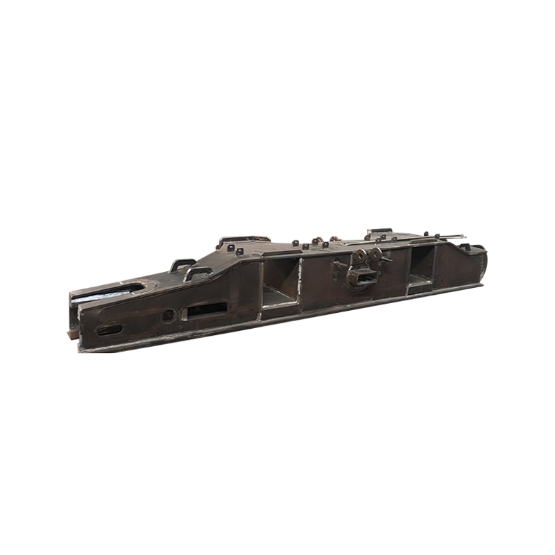
Our Crawler Crane Track Frame Carbon Steel Structural Parts are manufactured with controlled welding procedures and post-weld heat treatment where required to relieve residual stress and extend service life.
The Counterweight System: Managing Load Moment
No crane can lift a load at a radius without creating an overturning moment about the tipping axis. The counterweight system offsets this moment by placing substantial mass at the rear of the crane. On large crawler cranes, counterweight packages can weigh 200 tons or more and are often assembled in modular slabs to allow configuration changes for different lift requirements.
The structural components involved in the counterweight system include:
- Counterweight tray — the structural steel tray that holds and positions the weight slabs on the slewing table
- Superlift mast — on large cranes, an additional mast extending rearward that allows the counterweight to be suspended rather than resting on the slewing table, dramatically increasing load capacity at long radii
- Connection brackets and pins — high-tolerance pin joints that must resist both shear and bending under the full counterweight load
Comparison of Core Structural Components by Function
| Component | Primary Function | Dominant Load Type | Key Failure Risk |
|---|---|---|---|
| Boom | Extend reach, carry hook load | Compression + bending | Buckling, weld fatigue |
| Mast / Gantry | Control boom angle via pendants | Compression + tension | Column buckling |
| Slewing Table | Rotate upperworks, mount machinery | Bending + torsion | Distortion, bearing misalignment |
| Track Frame | Distribute load to ground | Bending + torsion | Fatigue cracking, deformation |
| Counterweight Frame | Offset overturning moment | Shear + compression | Connection pin wear |
Hoist Machinery Frame and Winch Mounting Structure
While the hoist drum and winch motor are mechanical components, the structural frame that mounts them to the slewing table is equally critical. During hoisting, the wire rope pulls upward on the drum, generating a reaction force that is transmitted through the mounting frame into the slewing table structure. A poorly designed or worn mounting frame allows the drum to flex under load, accelerating rope wear and reducing hoist accuracy.
Hoist frames are typically fabricated from structural steel plate, with bolted or welded connections to the slewing table. Gusset plates at connection points are essential to prevent local stress concentrations from initiating cracks after extended operation.
Structural Steel Grade and Welding Quality: Why They Matter More Than You May Think
Two cranes with identical dimensions and the same rated capacity can have dramatically different service lives depending on the steel grade and welding quality used in their structural fabrication. This is a point we see underestimated by buyers who focus primarily on price.
Consider the following practical comparison:
| Steel Grade | Typical Yield Strength | Weight Saving vs. Q345 | Typical Application |
|---|---|---|---|
| Q345 / S355 | 345 MPa | Baseline | Track frames, counterweight trays |
| Q460 / S460 | 460 MPa | ~25% | Slewing tables, hoist frames |
| Q690 / S690 | 690 MPa | ~50% | Boom chord members, mast sections |
Weight saving at the boom and mast level is especially valuable: every kilogram removed from the boom can directly translate to additional lifting capacity by reducing dead load at the end of the moment arm. This is not a minor consideration—on a large lattice boom crane, optimizing boom steel grade can add several percent to the rated load chart.
On the welding side, the difference between a certified weld procedure and an uncertified one shows up not at initial commissioning but after 3,000 to 5,000 operating hours, when fatigue cracks begin to appear at poorly executed weld toes. Full-penetration welds at critical joints, combined with visual and non-destructive testing (NDT), are the standard that reputable structural part manufacturers follow.
What to Look for When Sourcing Crane Structural Parts
If you are sourcing structural components for a crane rebuild, OEM replacement, or custom machine build, here are the critical questions to ask any supplier:
- Material certification — Can the supplier provide mill certificates for the steel plate used, confirming grade, heat number, and mechanical test results?
- Welding qualifications — Are welders certified to an international standard (e.g., ISO 9606, AWS D1.1)? Are weld procedures (WPS/PQR) documented and available?
- Dimensional tolerances — What are the stated tolerances for critical interfaces (pin bores, mounting surfaces, flange flatness)?
- NDT inspection — Are welds inspected by ultrasonic testing (UT) or magnetic particle inspection (MPI)? Is an inspection report provided with each component?
- Surface treatment — What corrosion protection system is applied, and does it meet the environmental requirements of your operating location?
A supplier who cannot answer these questions clearly should be treated with caution, regardless of price. Structural failures in cranes carry safety consequences that no project schedule or budget saving can justify.
As a manufacturer of heavy machinery structural components, we offer a full range of crane carbon steel structural parts—including track frames, slewing tables, and boom components—fabricated to documented procedures with material traceability and inspection records provided as standard.
Maintenance Considerations That Start With Structural Design
Good structural design anticipates maintenance. Components should be designed for access—inspection ports in hollow box sections, drain holes to prevent water accumulation, and painted surfaces that allow crack detection during visual inspection. Track frames, in particular, should have inspection covers at the carbody connections where fatigue cracking most commonly initiates.
A structured inspection program for crane structural components typically includes:
- Visual inspection every 250 operating hours — check for cracks, paint damage, corrosion, and deformation at all welded connections
- Pin and bore dimensional check every 1,000 hours — measure wear at all pivot pins and confirm bore diameter is within service limits
- NDT inspection at known high-stress locations every 2,000 hours — particularly boom heel connections, slewing table gusset welds, and track frame X-frame joints
- Full structural survey before major overhaul or recertification — typically every 5 years or after any overload event
Catching a developing crack at the visual inspection stage costs a fraction of the repair bill once the crack has propagated through a plate or weld. Structural maintenance is not a cost—it is the most cost-effective insurance available for heavy lifting equipment.