 +86-573-86868360
 Inquiry
 English
 Español
 عربى
عربى

Content
- 1 The Critical Role of Structural Components in Steam Turbines
- 2 Material Selection: Carbon Steel and Its Alloys
- 3 Manufacturing Precision: Machining and Assembly Tolerances
- 4 Common Structural Components and Their Specific Requirements
- 5 Quality Control and Testing Protocols
- 6 Corrosion and Wear Resistance Considerations
- 7 Sourcing and Supplier Evaluation
The Critical Role of Structural Components in Steam Turbines
When a steam turbine casing cracks after only 20,000 operating hours, the root cause is often not the base material but a structural component machined just 5 microns out of tolerance. These precision carbon steel parts—from high‑pressure cylinders to bearing pedestals—must withstand extreme thermal cycling and dynamic loads while maintaining perfect alignment. Even minor deviations can lead to catastrophic turbine failure.
Structural components form the backbone of every steam turbine. They hold the rotor assembly in place, channel high‑energy steam through the flow path, and absorb both axial and radial forces generated during operation. Without rigorous material selection and manufacturing control, efficiency drops and unplanned outages multiply. Power generation facilities rely on the integrity of each weld seam, bolt hole, and machined face to keep turbines running reliably for decades.
Material Selection: Carbon Steel and Its Alloys
Carbon steel remains the primary choice for turbine structural parts because it balances strength, weldability, and cost at the temperatures and pressures common in utility‑scale steam systems. Grades such as ASTM A36 and A516 are specified for low‑ and intermediate‑temperature sections, while low‑alloy steels (e.g., A387 Grade 11) appear where metal temperatures exceed 400°C. The carbon content typically stays below 0.25% to avoid welding‑induced cracking and to preserve toughness after post‑weld heat treatment.
Impact toughness at ‑20°C must exceed 27 J for critical structural components that operate near the ductile‑to‑brittle transition. Material mill test reports (MTRs) therefore become non‑negotiable; they verify heat chemistry, tensile strength, and Charpy values against project specifications. Any steel that fails to meet these thresholds risks brittle fracture during a cold start or transient thermal shock.
Weldability and Post‑Weld Heat Treatment
Large structural fabrications—such as inner cylinders and exhaust hoods—rely on full‑penetration welds with preheating between 150°C and 200°C to control hydrogen diffusion. After welding, the entire assembly undergoes stress‑relief annealing at 600–650°C for roughly one hour per 25 mm of thickness. This cycle reduces residual stresses that would otherwise distort the component during service and accelerate corrosion fatigue at the highly stressed corners.
Manufacturing Precision: Machining and Assembly Tolerances
After casting or forging, every structural piece passes through multi‑axis CNC machining to achieve the geometric accuracy a turbine demands. Flatness across cylinder split lines is held to 0.02 mm per meter, and bore concentricity for bearing seats typically stays within 0.05 mm total indicated runout. Such tight tolerances prevent steam leakage at the horizontal joint and maintain the rotor‑to‑stator clearances that directly affect turbine efficiency.
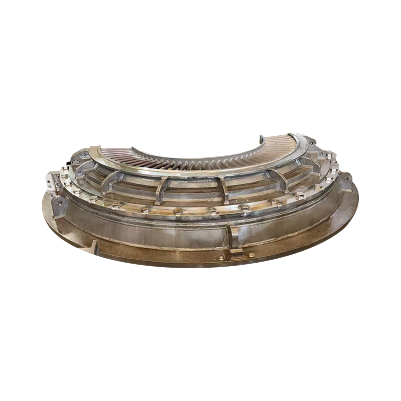
Diaphragm structural components present a special challenge. The groove that holds the nozzle ring must be concentric with the rotor centerline within a few hundredths of a millimeter. Misalignment here forces the rotor to rub against stationary parts, quickly eroding labyrinth seals and causing unplanned outages. Our carbon steel diaphragm structural parts are machined with dedicated fixturing that locks the workpiece into a known datum, ensuring repeatable accuracy across production runs.
Assembly is just as critical. When bolting up a two‑half casing, torque sequences and bolt stretch are monitored to distribute the clamping force uniformly. Uneven bolt loading can open a steam leak path within the first hundred operating hours, wasting energy and eroding the metal surfaces downstream.
Common Structural Components and Their Specific Requirements
Cylinders and Casings
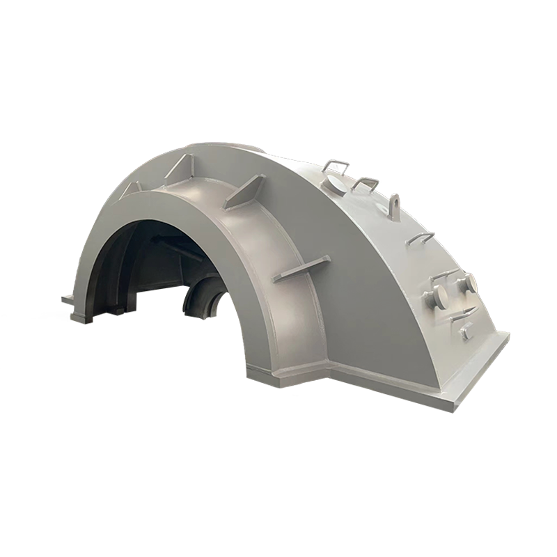
Turbine cylinders enclose the rotor and guide steam across the blade stages. They face the highest pressure differentials and therefore demand thick‑section plate that resists creep at elevated temperatures. A well‑designed cylinder integrates ribs and flanges that direct thermal expansion along controlled axes, preventing the ovalization that would scrape blade tips. Carbon steel turbine cylinder components must pass ultrasonic examination for lamination defects before any machining begins.
Bearing Seats and Pedestals
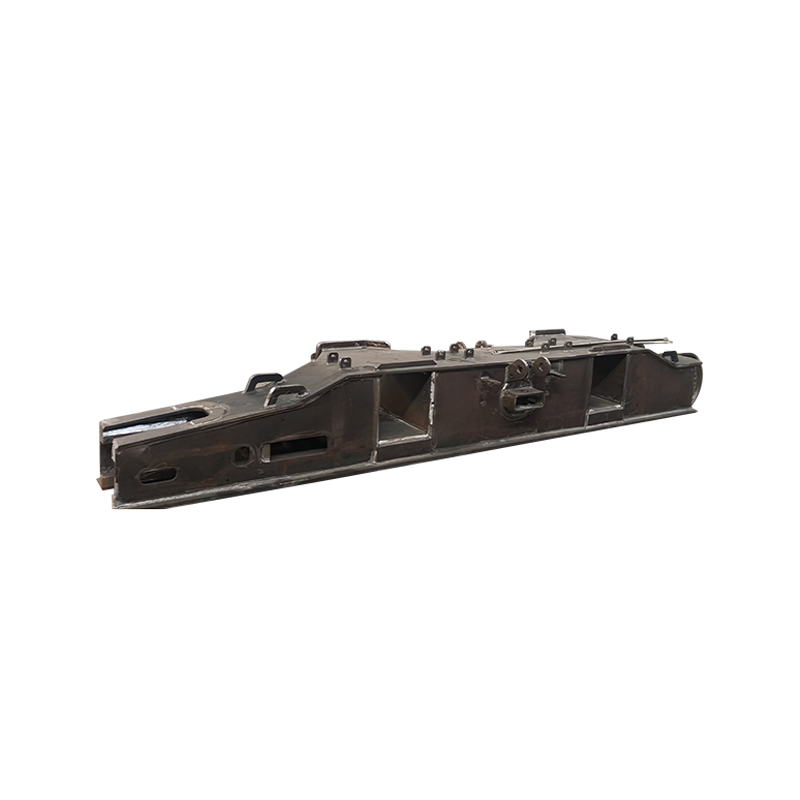
Bearing seats support the rotor weight and maintain alignment under both static and dynamic conditions. They transfer thousands of kilograms of load into the foundation, so their base plates must be flat within 0.05 mm per meter. Any settlement or warping changes the bearing oil‑wedge geometry and triggers high‑amplitude vibration. Steam turbine bearing seat structures are often fabricated from normalized carbon steel plate and then post‑machined on horizontal boring mills to guarantee parallelism between the bearing bore and the foundation interface.
Diaphragms and Guide Rings
Diaphragms hold the stationary nozzle partitions that direct steam onto the rotating blades. They slip into grooves machined inside the casing, so both the diaphragm outer diameter and the casing groove must be machined to a clearance of 0.15–0.30 mm—tight enough to minimize bypass leakage yet loose enough to allow thermal expansion. Guide rings perform a similar alignment function and are often hard‑faced with Stellite to resist erosion from wet steam.
Compensators and Expansion Joints
Thermal growth in a large steam turbine can exceed 15 mm. Compensators—either bellows or sliding joints—absorb this movement between fixed points, protecting adjoining pipework and casings from overstress. Their fabrication demands precise forming and welding to deliver the required cycle life without fatigue cracks.
Quality Control and Testing Protocols
Every structural component leaves the factory only after a series of non‑destructive and dimensional tests confirm that it meets the engineering specification. The following table summarizes the typical inspection regime for major part families.
| Component | Critical Property | Test Method | Acceptance Criteria |
|---|---|---|---|
| Cylinder / Casing | Weld integrity | Ultrasonic testing (UT) | No linear indications exceeding 3 mm |
| Bearing seat | Flatness of bearing bore | Coordinate measuring machine (CMM) | Flatness ≤ 0.05 mm/m |
| Diaphragm | Groove concentricity | Dial indicator on rotary table | TIR ≤ 0.05 mm |
| Compensator / Bellows | Leak tightness | Hydrostatic test | No leakage at 1.5 × design pressure for 30 min |
| All structural welds | Surface cracks | Magnetic particle (MT) or dye penetrant (PT) | No relevant linear indications |
Hydrostatic test pressure is 1.5 times the component’s maximum allowable working pressure, held for 30 minutes. This duration allows enough time for small weep holes or porosity to manifest, which might otherwise pass a quick visual check. Pressure decay monitoring adds an extra layer of reliability on critical sealing joints.
Corrosion and Wear Resistance Considerations
Carbon steel alone does not resist the steam chemistry found in many modern plants. Moist steam carries dissolved oxygen that can initiate pitting in hours. To counter this, structural components often incorporate a corrosion allowance—typically 1.5–3 mm of extra wall thickness—so that minor surface attack does not reduce load‑bearing capacity within the design life. In more aggressive environments, operators specify a cladding or coating; inorganic zinc silicate shop primer protects exposed surfaces during storage and installation, while epoxy phenolic linings guard internal flow passages against flow‑accelerated corrosion.
Wear resistance is equally important at bolted flanges and support feet, where fretting caused by micro‑movements can gall the steel. Hard‑chromium plating or the application of a sacrificial anti‑fretting compound dramatically extends the interval between overhauls. These measures are engineered into the component from the design phase, not added as an afterthought.
Sourcing and Supplier Evaluation
A robust supplier qualification process separates parts that will last 200,000 hours from those that will trigger a forced outage in the first year. Look for manufacturers that hold ISO 9001 certification as a minimum, but also verify ASME Section VIII or PED accreditations when the component forms a pressure boundary. Ask for documented welding procedure specifications (WPS) and procedure qualification records (PQR) for each joint configuration. The best shops maintain a full‑time welding engineer on staff and regularly calibrate their measuring instruments against NIST‑traceable standards.
Material traceability cannot be an option. Each piece of plate, forging, or pipe must be stamped with a heat number that ties back to the mill certificate. During the receiving inspection, 100% positive material identification (PMI) using X‑ray fluorescence ensures that no incorrect grade entered the supply chain. Only after all documentation is complete does the manufacturing begin.