 +86-573-86868360
 Inquiry
 English
 Español
 عربى
عربى

Content
The Structural Backbone of a Tunnel Boring Machine
Every millimeter of a tunnel boring machine's steel structure must resist forces that exceed thousands of tons. The cutter head, shield shell, and thrust frame are not static housings—they are dynamic load‑bearing systems that decide whether a TBM can advance through abrasive rock or squeezing ground without catastrophic deformation. When procurement engineers evaluate suppliers, the first filter should be the ability to deliver steel components that maintain dimensional stability under extreme torsion, thrust, and bending moments.
The steel structure is the TBM’s skeleton. Unlike off‑the‑shelf parts, these assemblies are typically fabricated in low‑volume, high‑mix batches that demand engineering‑grade structural design. A 2 mm misalignment in a shield segment can cause binding during assembly underground, while a crack in a thrust cylinder bracket can halt a multi‑million‑dollar project. Therefore, understanding the types, material properties, and fabrication tolerances of the core steel components is not optional—it is the basis for qualifying a supplier.
Core TBM Steel Structure Components Breakdown
Cutter Head Steel Structure
The cutter head is the primary excavation tool and the most mechanically aggressive steel assembly on a TBM. Its structural frame must hold disc cutters and scrapers in precise concentric arrays while rotating under face pressure. The main plate, spoke arms, and muck buckets are typically fabricated from high‑strength low‑alloy steel such as Q345B or Q420, often with a wear‑resistant overlay of Hardox 400/500 or equivalent. This dual‑material approach gives the structure bulk toughness while the surface withstands abrasion from quartz‑rich rock.
Welding is a make‑or‑break process here. The large‑diameter welds connecting the peripheral ring to the spokes must be full‑penetration, with ultrasonic and magnetic particle inspection applied to every critical joint. Machining tolerances for the cutter mounting pockets typically stay within ±0.1 mm to guarantee concentric tool paths. When sourcing cutter head structural parts, buyers should confirm that the fabricator has in‑house large‑capacity CNC boring mills and documented welding procedure qualification records (WPQR).
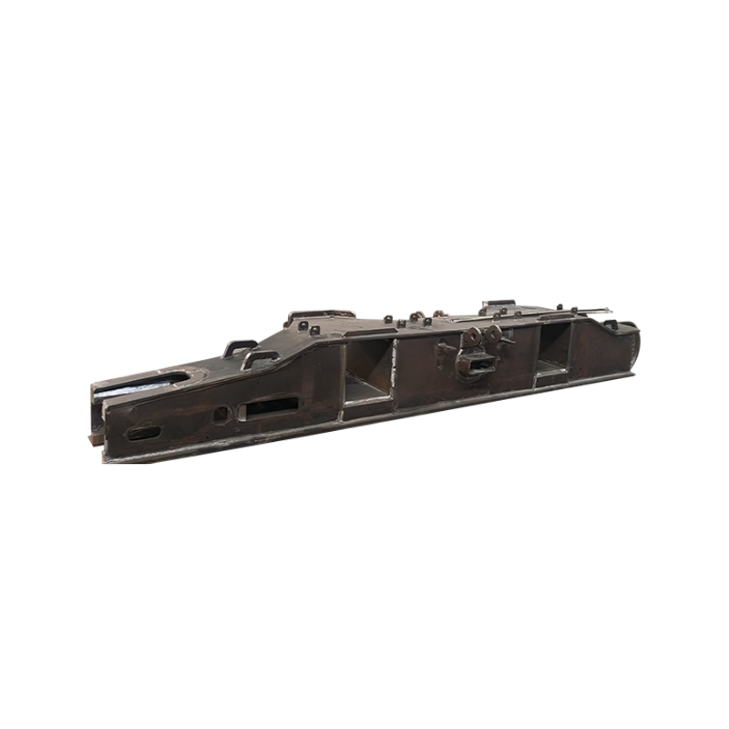
 Tunnel Boring MachineThe shield shell is ...View Product →
Shield Structure (Front, Middle, and Tail Shield)
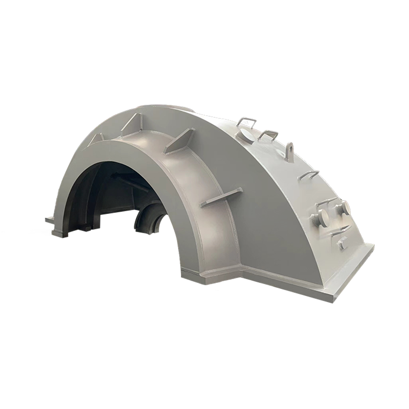
The shield is the mobile safety capsule. Built as a cylindrical steel shell, it supports the excavated perimeter while housing the main drive, articulation rams, and segment erector. Typically, the shield is split into front, middle, and tail sections for transport, then bolted and welded together on site. Wall thicknesses range from 40 mm to over 100 mm depending on ground pressure, with internal stiffener rings spaced at engineered intervals to prevent ovalization.
Manufacturing this structure requires precision rolling and the ability to maintain a circularity tolerance often below 0.5 % of the diameter. Post‑fabrication, each shield section undergoes a water‑tightness test at a specified pressure to verify girth welds and bolted flanges. A reputable supplier will offer shield machine shell components that are fully traceable to heat numbers, with third‑pfarty NDT reports covering 100 % of the longitudinal and circumferential seams.
 Tunnel Boring MachineThe shield shell is ...View Product →
Propulsion System Steel Frame (Thrust Cylinder Bracket)
Thrust brackets and the main push frame transfer tens of thousands of kilonewtons from the hydraulic cylinders into the segmental lining. These parts are typically fabricated from high‑yield steel grades such as Q550 or Q690D, selected for their combination of strength and notch toughness. The design must handle cyclic loading over thousands of strokes, so fatigue‑prone details like sharp corners or partial‑penetration welds are eliminated in favor of generous radii and full‑thickness connections.
Acceptance criteria for a shield machine frame and traveling mechanism should include dimensional reports from laser trackers and proof load testing on critical joints. The consequence of a bracket fracture is a stalled machine and an expensive intervention, so fatigue life assessment backed by finite element analysis is a non‑negotiable supplier capability.
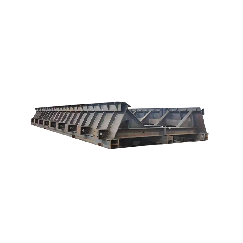 Tunnel Boring MachineThe shield shell is ...View Product →
Material Selection and Heat Treatment for TBM Steel Components
Commonly Used Grades of Carbon Steel
No single steel grade fits every TBM zone. The material choice depends on whether the part sees high wear, high static load, or cyclic stress. The table below lists grades frequently specified for heavy TBM structures.
| Grade | Typical Yield Strength (MPa) | Common Application |
|---|---|---|
| Q345B / S355J2 | 345 | Shield shells, structural stiffeners, non‑wear zones |
| Q420 / S420N | 420 | Cutter head structural core, main drive housings |
| Q690D / S690QL | 690 | Thrust brackets, articulation joints, high‑load frames |
| NM400 / Hardox 400 | — (wear plate, hardness ~400 HBW) | Cutter head face plates, muck scoops, bucket lips |
Raw material selection is only half the battle. Mill test certificates (EN 10204 3.1 or 3.2) must be cross‑checked against heat numbers stamped on the steel. Any supplier that cannot provide full material traceability for structural parts introduces unacceptable project risk.
The Importance of Heat Treatment in Enhancing Durability
Heat treatment transforms a good steel grade into a reliable component. For shield‑critical items, post‑weld stress relief (PWHT) is standard practice to reduce residual stresses that cause distortion or delayed cracking. In thrust components, quenching and tempering (Q&T) refines the grain structure, boosting toughness at sub‑zero temperatures often found in water‑pressurized tunnels.
The effect on service life is measurable. Properly normalized weldments can see a 20–30 % improvement in fatigue resistance compared to as‑welded conditions. As explained in our detailed analysis of heat treatment and shield machine durability, narrow control over heating rate, holding time, and cooling rate is essential. A supplier that can demonstrate in‑house furnace charts and hardness mapping for each main seam adds a layer of confidence that field inspections alone cannot provide.
Quality Assurance: How to Verify Your TBM Steel Components Supplier
Essential QC Measures: Non‑Destructive Testing and Dimensional Inspection
A qualified TBM steel fabricator integrates quality checks into every production stage, not just final inspection. Non‑destructive testing (NDT) is the primary language of verification. Ultrasonic testing (UT) detects subsurface flaws in thick plates, while magnetic particle (MT) and dye penetrant (PT) inspections locate surface‑breaking cracks on finished welds. The scope should be clearly defined in an inspection and test plan (ITP) before cutting the first plate.
Dimensional control is equally critical. Portable arm CMMs and laser trackers measure mating surfaces, bolt‑hole patterns, and overall envelope within tenths of a millimeter. Buyers should ask to see sample reports and compare them with the project’s tolerance tables. For additional guidance, refer to the common quality control measures during production that experienced heavy‑steel fabricators employ. The presence of a detailed, client‑approved ITP is a stronger indicator of reliability than a simple ISO 9001 certificate.
High‑Precision Fabricating for TBM Safety
TBM steel parts are not just heavy—they are geometrically complex. Shield segments often require simultaneous boring of trunnion seats and threaded holes on opposite sides with alignment tolerances under 0.2 mm over several meters. Achieving this demands large‑capacity CNC floor‑type boring mills and 5‑axis machining centers capable of handling components that weigh over 50 tons.
The consequences of sloppy machining go straight to safety. A misaligned articulation pin can seize, and an out‑of‑round shield can gouge the excavated wall, increasing friction and wear. A dedicated high‑precision fabricating for TBM safety approach includes in‑process checks, temperature‑controlled machining environments, and assembly trials that simulate the final bolted interface before shipping. These steps are not optional add‑ons; they define the difference between a supplier who builds to print and one who builds for function.
Choosing the Right Partner for Your TBM Project
The steel structure of a tunnel boring machine is the physical link between excavation power and ground support. When that link is compromised, shut‑downs consume schedule and budget far beyond the cost of the parts themselves. A capable partner will bring more than welding; they bring documented metallurgical know‑how, comprehensive NDT programs, and the heavy‑machining capacity to meet the tightest envelope requirements.
Procurement teams should base evaluations on hard engineering evidence: mill certificates tied to heat numbers, weld maps, post‑weld heat treatment charts, and first‑article dimensional reports. By insisting on these deliverables up front, you shift the conversation from price‑per‑kilogram to life‑cycle reliability—the only metric that matters underground.