 +86-573-86868360
 Inquiry
 English
 Español
 عربى
عربى

Content
- 1 The Foundation: Defining the Track Frame and Its Components
- 2 Primary Function 1: Distributing Immense Loads and Bending Moments
- 3 Primary Function 2: Providing a Stable and Level Base for Lifting Operations
- 4 Primary Function 3: Serving as the Mounting Platform for the Drive and Undercarriage System
- 5 Primary Function 4: Enabling Controlled Mobility Under Extreme Weight
- 6 Conclusion: The Unsung Hero of Crane Integrity
In the world of heavy lifting, the crawler crane stands as a titan of stability and power. While the boom, hoist, and cab often capture attention, the true foundation of its capability lies hidden beneath the massive structure: the track frame and its associated crawler crane track frame carbon steel structural parts. These components are not mere platforms; they are the critical, integrated system that transforms immense power and load into controlled, safe, and mobile operation.
The Foundation: Defining the Track Frame and Its Components
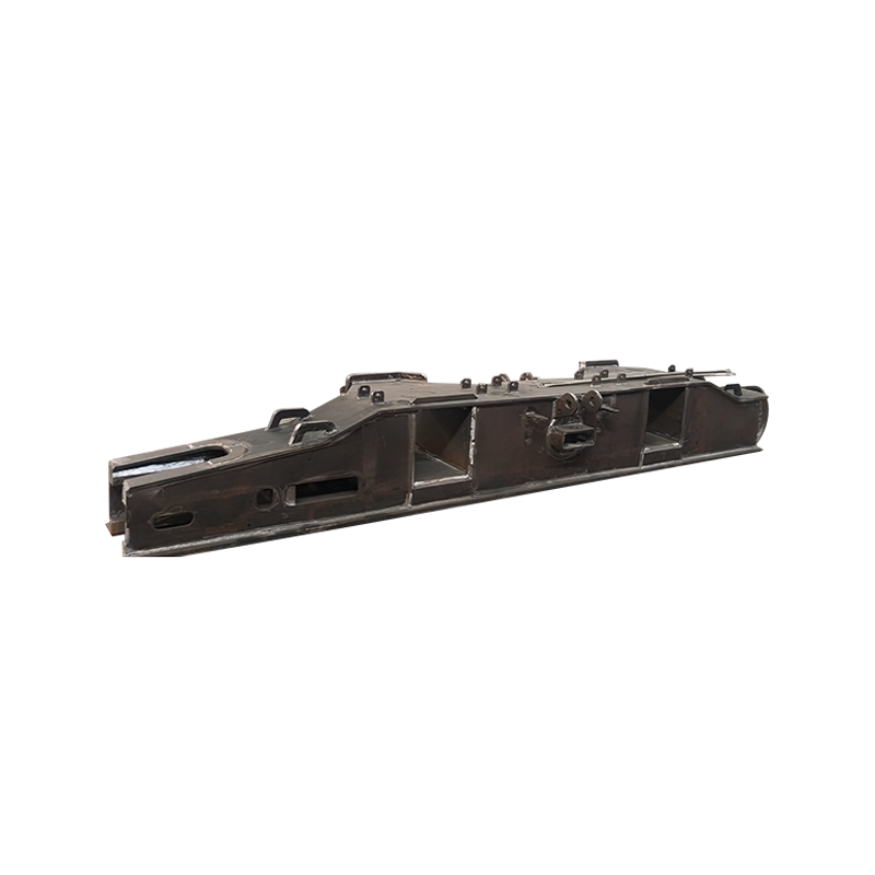
Before understanding their functions, it’s essential to identify the key parts in question. The track frame, also known as the car body or carbody, is the primary steel structure that forms the crane’s lower works. It is the chassis to which everything is attached. Integral to this frame are critical carbon steel structural parts, including:
- Main Beams and Cross Members: The longitudinal and transverse elements that form the rigid, box-like structure.
- Sprocket and Idler Mounting Points: The reinforced housings that support the drive sprockets and front idlers around which the track chains rotate.
- Roller Frames/Crawler Side Frames: The sturdy arms that hold the bottom rollers, which carry the crane’s weight along the track chain.
- Connection Points for the Upperworks: The massive, machined surfaces and pivot points where the crane’s rotating upper structure (the house) is mounted.
Manufactured from high-yield strength carbon steel, these parts are engineered to withstand phenomenal stresses through a combination of robust design, precise welding, and rigorous quality control.
Primary Function 1: Distributing Immense Loads and Bending Moments
The most fundamental role of the track frame structure is to act as a load-distribution hub. It must manage forces from multiple directions:
- Vertical Load from Hoisting: The entire weight of the lifted load, the boom, and the crane’s own upperworks is transferred down through the centerpiece and onto the track frame. The main beams and cross members are designed to resist bending under this colossal weight, preventing catastrophic deflection.
- Dynamic and Shock Loads: Lifting, swinging, and lowering loads create dynamic forces far greater than the static weight. The carbon steel structure must have the necessary tensile strength and fatigue resistance to absorb these shocks over thousands of cycles without cracking.
- Bending Moments from Boom Operations: When the boom is extended and lifts a load at a radius, it creates a powerful overturning moment—a force trying to tip the crane over. The track frame, with its wide stance, translates this moment into a combination of vertical compression on the side under the load and potential uplift on the opposite side. Its rigidity is what ensures this force is managed predictably and safely.
Without a track frame engineered to distribute these loads, the crane’s components would be subjected to point loads they cannot bear, leading to rapid failure.
Primary Function 2: Providing a Stable and Level Base for Lifting Operations
Stability is the non-negotiable currency of crane operation. The track frame is the primary provider of this stability through two key attributes:
- A Wide, Fixed Stance: Unlike mobile cranes with outriggers, a crawler crane’s stability is derived from the permanent, wide footprint of its tracks. The track frame’s design determines this footprint. Its width and length are calculated to provide a stable base that counteracts the overturning moments generated during lifting, ensuring the crane remains grounded and level.
- Ground Pressure Distribution: This is a critical, often overlooked function. The immense weight of the crane and its load is transferred from the track frame, through the roller frames, onto the track chains, and finally to the ground. The large surface area of the tracks, a direct result of the frame’s dimensions, distributes this weight as ground pressure. By significantly reducing pounds per square inch (PSI), the track frame enables the crane to operate on softer soils and unstable terrain where wheeled vehicles or cranes with smaller outrigger pads would sink.
Primary Function 3: Serving as the Mounting Platform for the Drive and Undercarriage System
The track frame is not a passive platform; it is the active backbone for the crane’s mobility system. It provides the rigid, precisely aligned mounting points for all components of the crawler system:
- Sprocket and Idler Alignment: The drive sprockets (at the rear) and idlers (at the front) must be perfectly aligned to ensure the track chain runs true. Misalignment, caused by a warped or poorly manufactured frame, leads to rapid, uneven wear on the track pins, bushings, and rails, as well as potential “derailing.”
- Bottom Roller and Carrier Roller Support: The roller frames, which are integral structural parts of the track frame, hold the bottom rollers that carry the machine’s weight. They must maintain a straight line to support the track chain evenly. The frame also supports the carrier rollers that keep the top of the track chain from sagging excessively.
Any flex or “walk” in the track frame under load would destroy this precise alignment, leading to inefficient power transmission, accelerated component wear, and a high risk of track failure.
Primary Function 4: Enabling Controlled Mobility Under Extreme Weight
A crawler crane’s ability to move with a load is a key advantage. The track frame makes this possible by integrating the power of the drive system with the stability of the base.
- Transmitting Propulsive Force: The torque from the travel motors is transferred to the sprockets, which pull the track chains. This force is reacted against the ground, propelling the crane. The track frame must be strong enough to handle this torsional and thrust force, especially when turning or climbing a grade under load.
- Facilitating Steering and Counteracting Torsion: During turns, especially “pivot turns” where one track moves forward and the other backward, the track frame is subjected to immense torsional (twisting) forces. Its box-section design, reinforced with gussets and robust cross members, provides the torsional rigidity needed to resist these forces without deformation.
Conclusion: The Unsung Hero of Crane Integrity
The crawler crane track frame and its carbon steel structural parts are a masterpiece of applied mechanical engineering. They are not simple slabs of metal but a highly engineered system that performs a symphony of critical functions simultaneously: distributing crushing loads, providing an unwavering foundation, supporting a complex drive system, and enabling controlled mobility. The selection of high-strength carbon steel is fundamental, offering the ideal balance of strength, toughness, weldability, and cost-effectiveness required for such a demanding application. When a crawler crane lifts a monumental load with steady precision, it is a direct testament to the integrity and performance of its foundational structure—the robust, reliable track frame.